
GRIDFINITY The 42 mm grid – explained
Gridfinity is one of the best examples of what a standard can do. A simple grid of 42 mm, a height unit of 7 mm – and every bin fits into every drawer, no matter who designed it.
It was created by Zack Freedman and is open source. It is not a YEZT standard, but it is the one every other standard has to live up to. So I rebuilt it in Fusion and wrote down the numbers – and what to think about when you build for the grid.
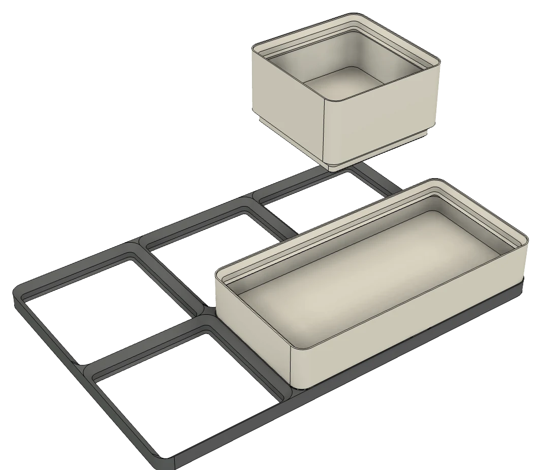
How it works
Three parts, one idea: everything sits on the same 42 mm grid.
1 · Baseplate
The grid on the floor of your drawer. Every cell is 42 × 42 mm and has a stepped, slanted wall – that profile is what holds the bins in place.
2 · Bins
Any size of n × m cells, any height in 7 mm steps (called u). Every cell has the same foot underneath, so a bin drops into the baseplate in any direction – optionally held by magnets.
3 · Stacking
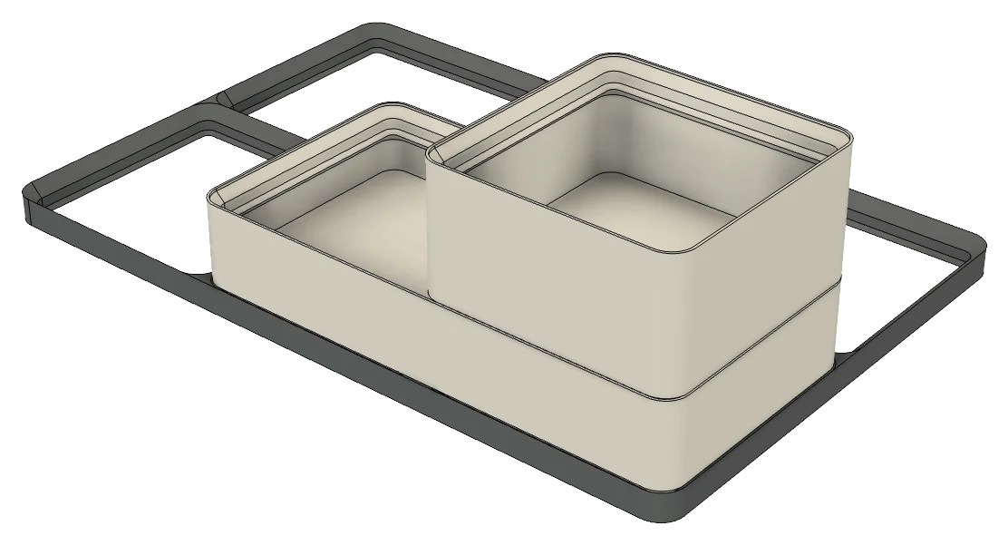
The optional lip on top of a bin has the same profile as the baseplate. Bins stack on top of each other – every bin is a little baseplate itself.
The Standard
Stick to these numbers and your bins fit into everybody else’s baseplates. All measurements in mm, all slopes 45°.
| Gridfinity | |
|---|---|
| Grid | 42 × 42 per cell |
| Height unit (u) | 7 |
| Bin outside | 42 × n − 0.5 (1 × 1 = 41.5) |
| Bin height | 7 × u, lip on top (+4.4) |
| Baseplate profile | 0.7 / 1.8 / 2.15 = 4.65 |
| Bin foot | 0.8 / 1.8 / 2.15 = 4.75, solid up to 7 |
| Corner radius | baseplate 4, bin 3.75 |
| Wall | min. 0.95, dividers 1.2 |
| Stacking lip | 0.7 / 1.8 / 1.9 = 4.4 |
| Magnets (optional) | Ø 6 × 2 in a Ø 6.5 × 2.4 hole |
| Magnet position | 13 from the cell center (26 apart) |
| Screws (optional) | M3 |
Build a Bin
Open Fusion and start a new design. This is a 1 × 1 × 3 bin – the same steps work for every size. Shortcuts: R rectangle, E extrude, D dimension.
The Foot
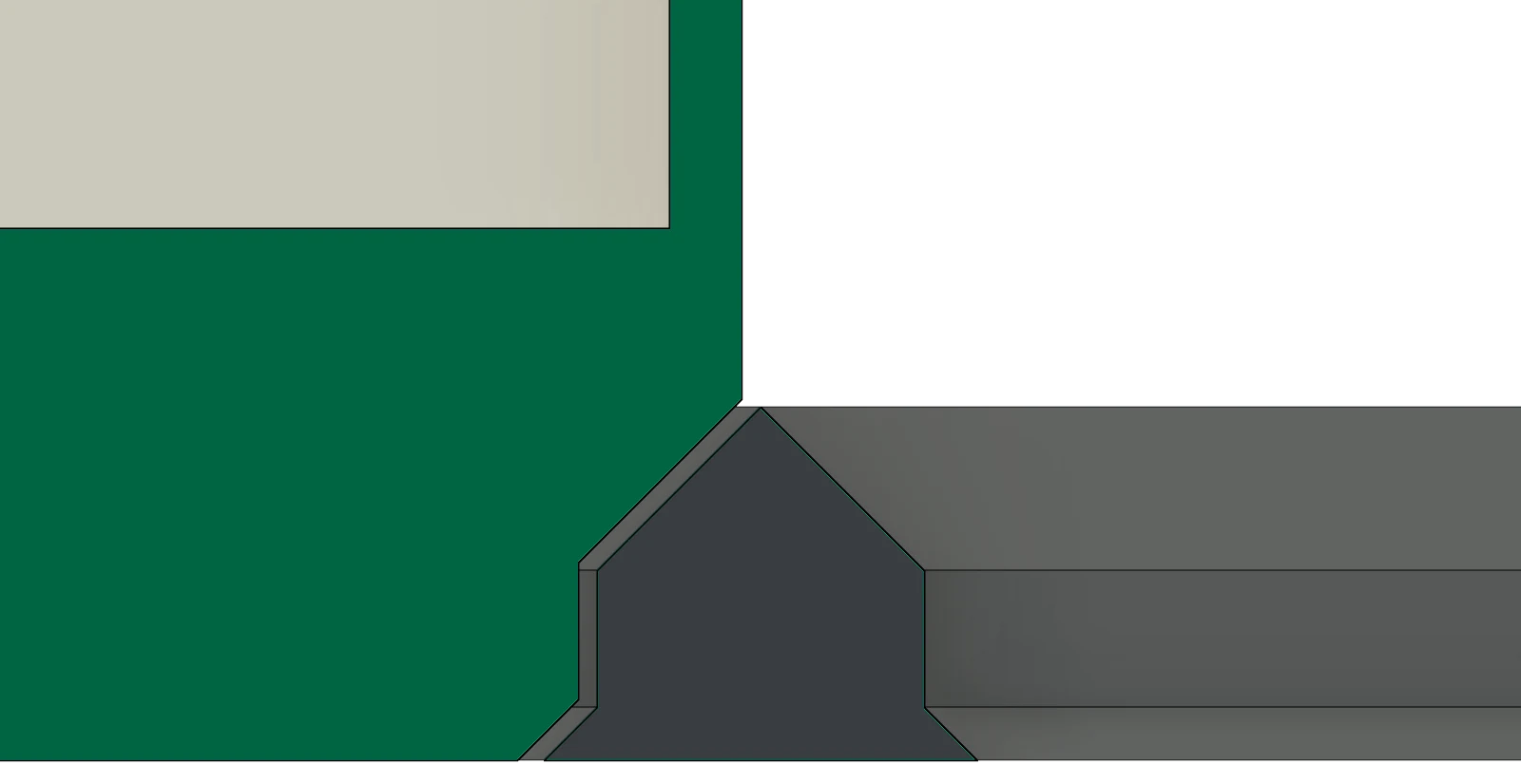
The foot is three layers, built from the bottom up. Sketch centered squares with rounded corners on offset planes and connect them with Loft:
35.6square, cornersr 0.8at0 mm37.2square, cornersr 1.6at0.8 mmand again at2.6 mm41.5square, cornersr 3.75at4.75 mm
Loft 0 → 0.8, extrude 0.8 → 2.6, loft 2.6 → 4.75. That gives the 45° steps – they have to match the baseplate, otherwise the bin rocks.
Body & Inside
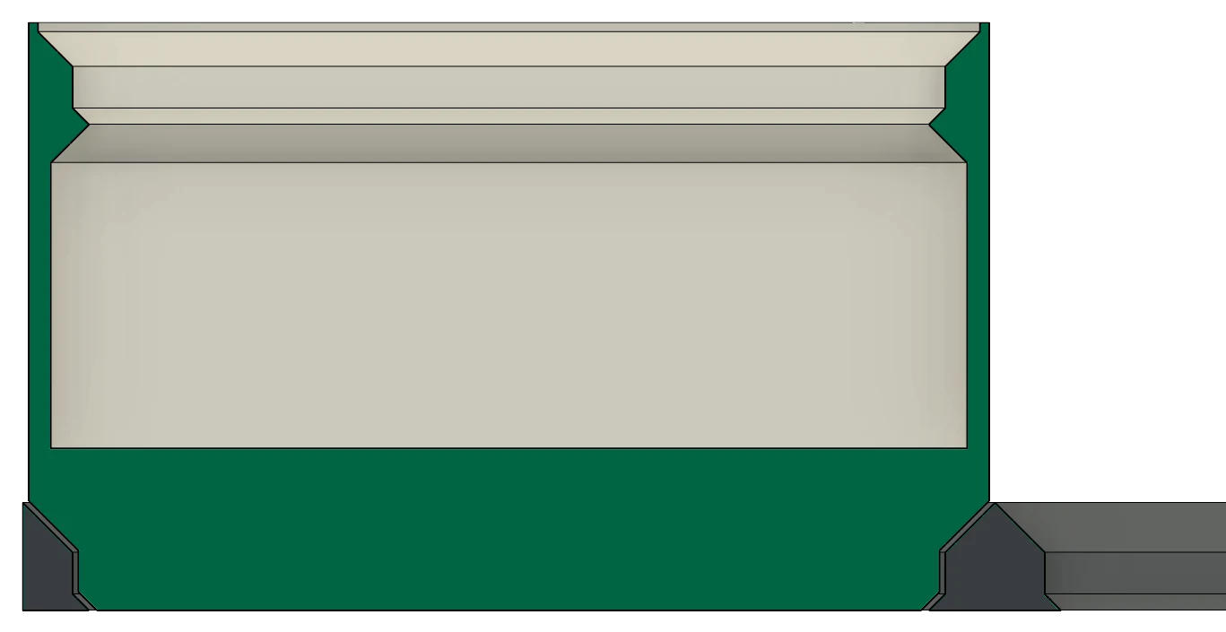
On top of the foot: the 41.5 square with r 3.75, extruded to 7 × u – for 3 u that is 21 mm (plus 4.4 if you want the lip).
Now hollow it: sketch the square 0.95 mm smaller on every side (39.6, r 2.8) and cut it down to 7 mm. The first 7 mm stay solid – that is the base, and it counts as the first u.
Stacking Lip
Optional, but nice: sketch the lip profile on a plane through the wall – 0.7 up at 45°, 1.8 straight, 1.9 at 45° to the outer edge – and use Sweep (Cut) along the top edge. Below the lip a 45° chamfer back to the wall, so it prints without supports.
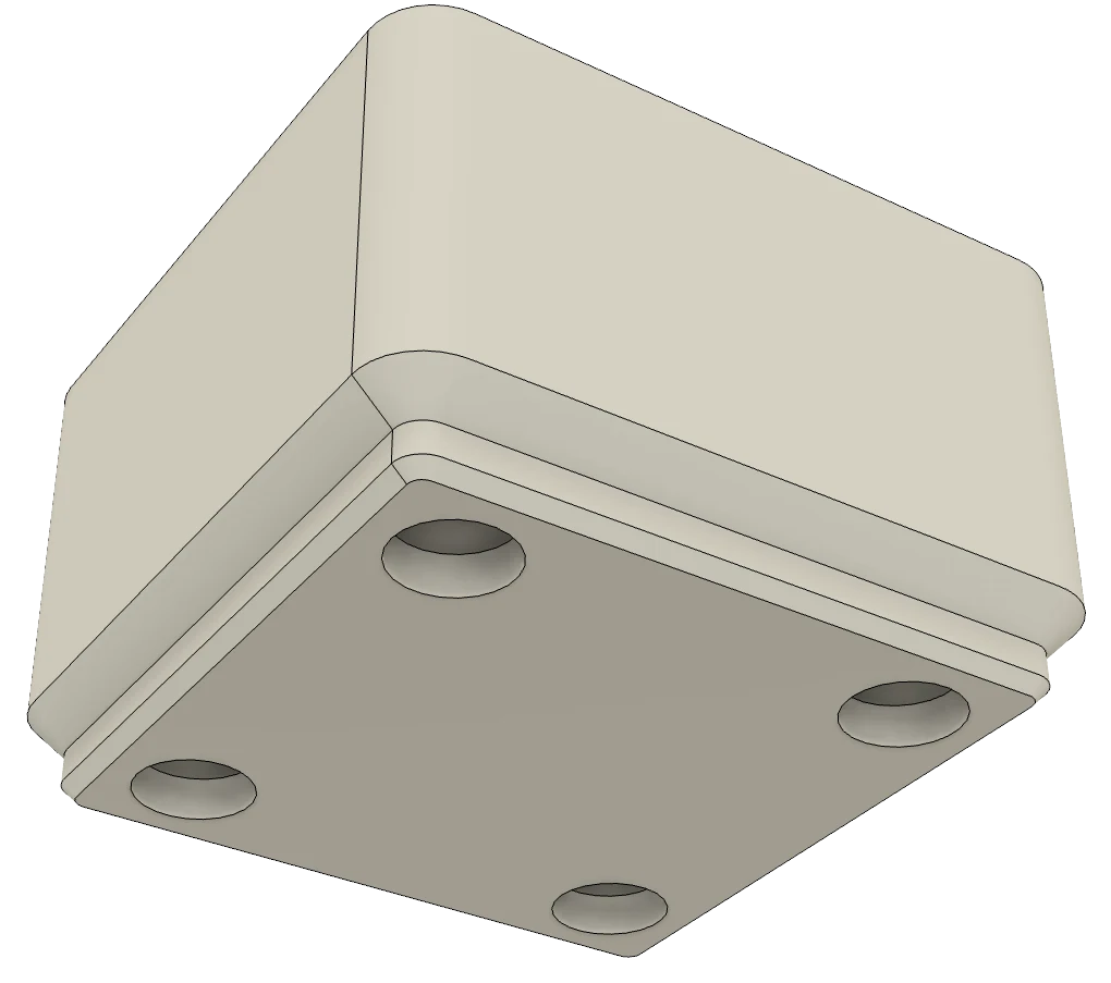
Magnets
Flip the bin over. Four 6.5 mm circles, each 13 mm from the center in both directions, cut 2.4 mm deep. That is a 6 × 2 mm magnet plus two layers of room.
Right-click the body → Save As Mesh and off to the slicer.
Bigger bins
For n × m bins: one foot per cell, patterned at 42 mm, and the body 42 × n − 0.5 by 42 × m − 0.5. A 2 × 1 bin is 83.5 × 41.5 mm – never 84.
What to think about
Worth knowing before you print your first bin.
The 0.5 mm rule
A bin is always 0.5 mm smaller than its grid: 0.25 mm of air on every side. Design to 42 × n and your bins will jam. The gap is in the close-up above – that is all the tolerance there is.
Heights in 7 mm
Everything goes up in 7 mm steps. The lip sits on top and is not counted – a 3 u bin is 21 mm, with lip 25.4 mm. The usable space inside starts at 7 mm.
Elephant’s foot
If your first layer squishes out, the bottom of the foot gets wider and the bin sits too high. Turn on elephant foot compensation in the slicer or print a 1 × 1 × 1 test bin first.
Walls & nozzle
0.95 mm walls are two perimeters with a 0.4 mm nozzle. Thinner walls print badly, thicker ones cost space – check the preview in the slicer.
Magnets
6 × 2 mm magnets need a 6.5 hole – press them in or add a drop of glue. Bins in a steel drawer don’t care about polarity; magnets in the baseplate do, so keep them all the same way round.
Measure the drawer
Drawer width ÷ 42, rounded down = number of cells. The rest is padding at the edge. If the baseplate is bigger than your print bed, split it into tiles – they just sit next to each other.
Credits & Sources
Gridfinity was designed by Zack Freedman and is released under the MIT license. The numbers on this page follow the community specification and the reference model gridfinity-rebuilt-openscad – I only rebuilt and explained them. Samples modelled in Fusion for this page.
Your Build?
Built something for the grid or found a number that doesn’t fit? Let me know!